Products

Macro Fiber Composite™ – MFC

The leading low-profile actuator, sensor and generator device

Flexible, durable and reliable

Increased strain actuator efficiency

Directional actuation and sensing

Damage tolerant

Conforms to surfaces

Various piezo ceramic materials available

Smart Material – Home of the MFC

The Macro Fiber Composite™ (MFC) is the leading low-profile, cost-competitive actuator, sensor or generator device offering high performance, flexibility and reliability.

The MFC was invented by NASA in 1999. In 2002, Smart Material started commercializing this invention worldwide as NASA’s licensed manufacturer and distributor. Since then, we have continued to improve and customize the MFC to fit the specific needs of our customers and to meet the requirements of new applications.

By 2021, we counted more than 1,300 MFC publications worldwide, documenting various applications, MFC properties and reliability.

MFC Types

The MFC’s are available in 3-3 and 3-1 operational modes. This is a unique feature of the Macro Fiber Composite.

MFC P1 type –
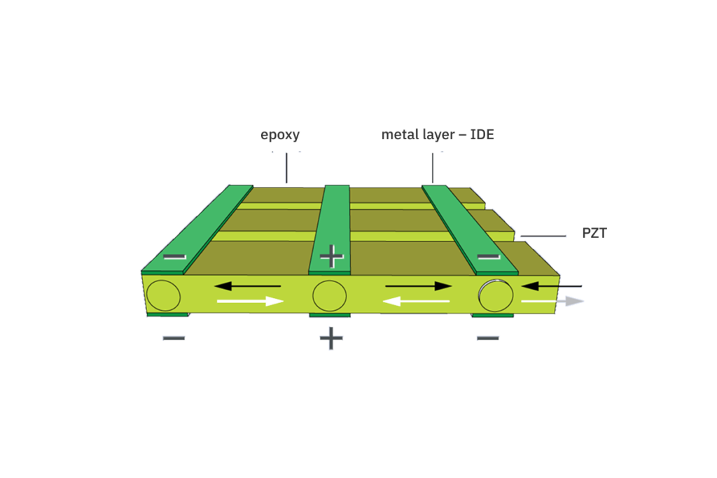
d33 operational mode

P1 type MFCs, including the F1 and S1 types, utilize the
d33 effect for actuation. They will elongate up to 1800ppm when operated at the maximum voltage rate of -500V to +1500V. As sensor thr P1- MFC shows a typical sensitivity of about 400 pC/N.

MFC P2 and P3 type – d31 operational mode

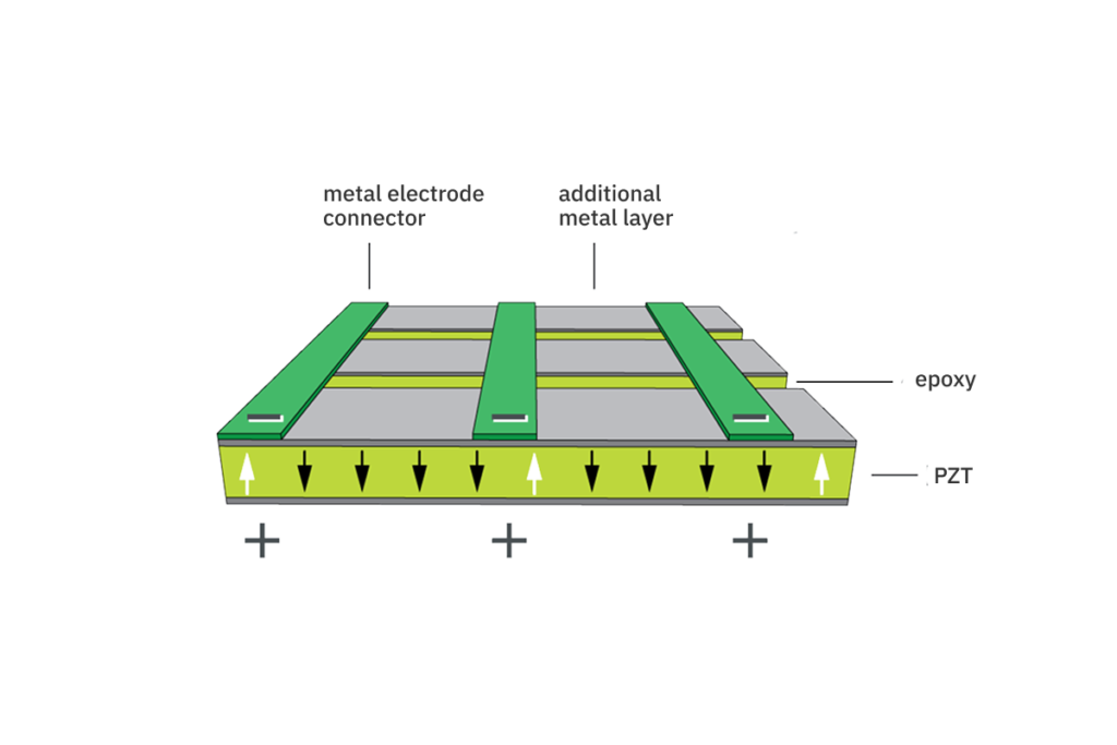
P2 and P3 MFCs use the
d31 effect for actuation, sensing and charge generation. They contract up to 750ppm when operated at the maximum voltage rate of -60V to +360V. As strain sensor they show a sensitivity of 200 pC/N. Both P2 and P3 MFCs are most commonly used for energy harvesting (PEH) and as strain sensors.

MFC Custom Design

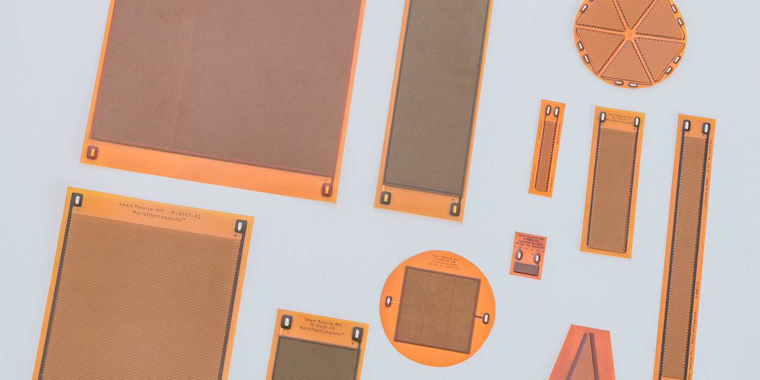
In addition to manufacturing Macro Fiber Composites in a variety of standard sizes, we also offer numerous specialized MFC layouts. Specialty MFCs have more complex designs, including arrays of single MFCs, and also allow electronic components to be integrated with the MFC.

How do MFC work?

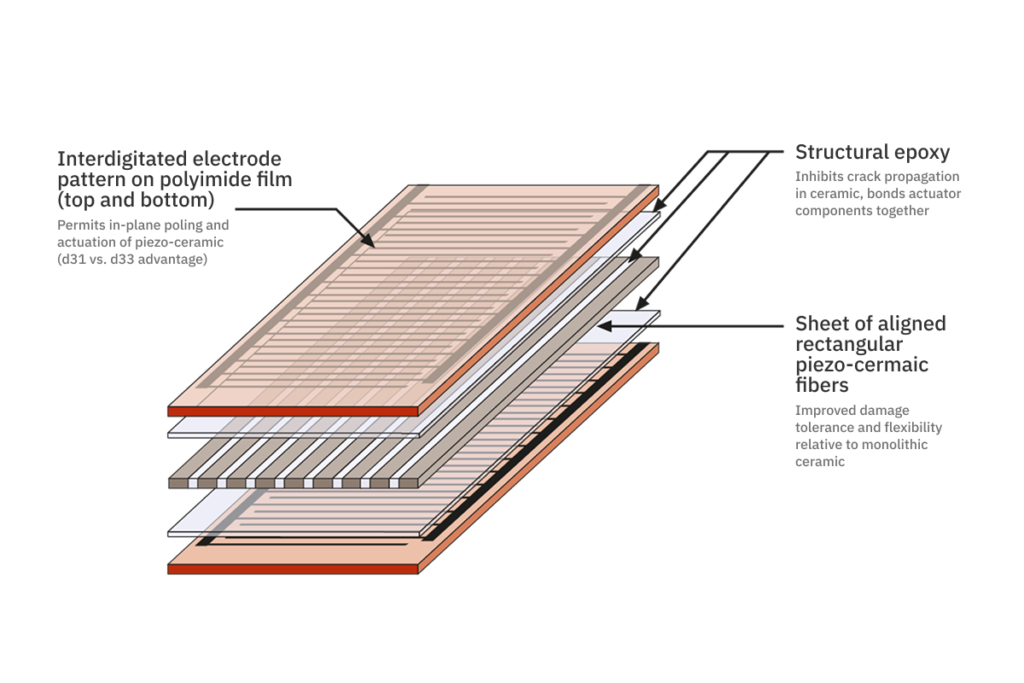
The MFC consists of rectangular piezo ceramic rods sandwiched between layers of adhesive, electrodes, and polyimide film.

MFC as Actuator, Sensor and Energy Harvester

The MFC can also be applied (usually bonded) as a thin, surface-conformable sheet to various types of structures, or embedded in a composite structure. If voltage is applied, it works as an actuator, bending or distorting materials, counteracting vibrations, or generating vibrations. When no voltage is applied, it can act as a very sensitive strain gauge, sensing deformation, noise and vibration. The MFC is also an excellent device for harvesting energy from vibrations.

MFC P1 type

The electrodes are attached to the film in an interdigitated pattern which transfers the applied voltage of the MFC structure directly to and from the ribbon-shaped rods. This assembly enables in-plane poling, actuation, and sensing in a sealed and durable ready-to-use package. sealed and durable ready-to-use package.

MFC P2 type

Between the inderdigitated finger layer and the composite cernel additional aconductive layers are applied on bothe sides. The applied or generated voltage generates an electrical field through the thickness of the piezoceramic rods. The interdigital electrodes of each level are connected to each other. They act as a redundant collecting electrodes.

General specifications

For an overview of some of the typical features of MFC, see the table below.

Blocking force (max.)

28N to 1kN

depending on width of MFC

Operating voltage (max.)

P1, S1, F1: -500V – 1500V

P2, P3: -60V – 360V

P2 Single Crystal: 0V – 500V

Operating frequency (max.)

Actuator: 10kHz

Sensor, Harvester <1MHz

Lifetime (avg.)

Actuator: 10E+9 cycles

Sensor: 10E+11 cycles (< 400ppm)

Harvester:10E+10 cycles (< 600ppm)

Thickness (avg.)

300µm, 12mil

Capacitance (avg.)

P1, S1, F1: 2nF – 12nF

P2, P3: 25nF – 200nF

MFC Engineering Properties

High-field (|E| > 1kV/mm),

biased-voltage-operation piezoelectric constants:

d33 P1 type, in rod direction

4.6E+02 pC/N

4.6E+02 pm/V

d31 P2 type, in electrode direction

-2.1E+02 pC/N

-2.1E+02 pm/V

Low-field (|E| < 1kV/mm > 300V),

unbiased-operation piezoelectric constants:

d33 P1 type, in rod direction

4.0E+02 pC/N

4.0E+02 pC/N

d33 P1 type, in rod direction

-1.7E+02 pC/N

-1.7E+02 pC/N

Average free-strain per volt

(low-field – high-field) for d33 P1 type 

in rod direction

~ 0.75 – 0.9 ppm/V

~ 0.75 – 0.9 ppm/V

Average free-strain per volt

(low-field – high-field) for d31 P2 type 

in rod direction

~1.1 – 1.3 ppm/V

~1.1 – 1.3 ppm/V

Free-strain hysteresis in rod direction

~ 0.2

~ 0.2

DC poling voltage, Vpol for d33 P1 type

+1500V

+1500V

DC poling voltage, Vpol for d31 P2 type

+360V

+360V

Poled capacitance @ 1kHz, room temp,
Cpol for d33 P1 type

~ 0.30 nF/cm²

~ 1.94 nF/in²

Poled capacitance @ 1kHz, room temp,
Cpol for d31 P2 type

~ 7.8 nF/cm²

~ 50 nF/ in²

Orthotropic Linear Elastic Properties

(constant electric field):

Tensile modulus, E1 in rod direction

30.336 GPa

4.4E+06 psi

Tensile modulus, E1 in electrode direction

15.857 GPa

2.3E+06 psi

Poisson’s ratio, v12

0.31

0.31

Poisson’s ratio, v21

0.16

0.16

Shear modulus, G12 rules of mixture estimate

5.515 GPa

8.0E+05 psi

Operational Parameters:

Maximum operational positive voltage 

Vmax for d33 P1 type

+1500

+1500V

Maximum operational positive voltage 

Vmax for d31 P2 type

+360V

+360V

Maximum operational negative voltage 

Vmin for d33 P1 type

-500V

-500V

Maximum operational negative voltage 

Vmin for d31 P2 type

-60V

-60V

Linear-elastic tensile strain limit¹

1000 ppm

1000 ppm

Maximum operational tensile strain¹

< 4500 ppm

< 4500 ppm

Recommended tensile strain for Energy Harvesting

< 600 ppm

< 600 ppm

Peak work-energy density

~48800 Nm/m³

~7 in-lb/in³

Temperature and Lifetime Parameters:

Minimum operating temperature

all Versions

-35°C

-31°F

Maximum operating temperature

Standard Version

< 85°C

< 176°F

Maximum operating temperature

HT Version

< 130°C

< 266°F

Operational lifetime (@ 1kVp-p)

> 10E+09 cycles

> 10E+09 cycles

Operational lifetime (@ 2kVp-p, 500VDC)

> 10E+07 cycles

> 10E+07 cycles

Operational Bandwidth:

Operational bandwidth as actuator

high electric field

0Hz up to 10 kHz

0Hz up to 10 kHz

Operational bandwidth as actuator

low electric field levels

(< 33% of max operating voltage)

0Hz up to 700kHz

0Hz up to 700kHz

Operational bandwidth as sensor

0Hz up to 1 MHz

0Hz up to 1 MHz

Additional mechanical parameters:

Thickness of all MFC types

300µm, +-10%

12 mil +-10%

Volume Density, active area

5.44 g/cm³

5.44 g/cm³

Area Density, active area

0.16 g/cm²

0.16 g/cm²

1 For further details please download the following publication “Nonlinear Tensile and Shear Behavior of Macro Fiber Composite Actuators”.

Downloads

Department of Mechanical Engineering, Virginia Tech, Blacksburg, Virginia

MFC Work Modes:
Expansion, Bending, Torsion
Resources

Resource Center & FAQs

Have a question or need more information? Find answers to frequently asked questions and additional insights in our Resources section.

FAQs

Browse our FAQ section for quick answers to the most common questions and other helpful information.

Downloads

Find a collection of general information and deeper insights into our products available for download.

References & Publications

Explore our references and publications for a deeper insight into our materials and projects.

Applications

Typical applications for Macro Fiber Composites

Learn more about typical applications using Macro Fiber Composites.

Shape Morphing of Airfoils and Structures

MFC actuators enable real-time shape changes in airfoils, improving aerodynamics, fuel efficiency, and control in aerospace applications.

P.A.S.S. –
Piezo Anti Ice Smart Skin

A lightweight, energy-efficient smart skin using piezoelectric vibrations to prevent ice formation on aircraft wings and UAV surfaces.

Vibration Control

MFC-based damping systems reduce unwanted vibrations in aircraft, vehicles, and industrial machinery, enhancing safety and durability.